
A Halo 4 Stack for 70cm on the Cheap
After having played in the weak signal portions of 6 and 2m I wanted to do some weak signal experiments on 70cm. My radio has the band, but my antenna orchard didn't have anything that would play on that band very effectively. It was time to correct that.
Why a Halo 4 Stack?
I don't have a tower or mast to mount a yagi antenna with a rotator on, so something that would be omni directional and horizontally polarized was my aim. Since I had good luck with my halos hanging in the trees for 6 and 2 meters, I decided I would try a similar solution for 70cm.
On 70cm, losses -- especially feed line losses -- accumulate quickly. If you have to run any appreciable length of lower quality feed line, say more than 20 feet or so, you may have lost an interesting signal before it even had a chance to reach the receiver. Also, transmitting power is often limited on this band. For instance, my FT-897 radio delivers only 20 Watts on this band. While you'd think that would be good for a few local contacts, a feed line loss of 6dB (40ft of RG-58 at 450MHz) means that only 5 Watts will arrive at the antenna. That's a lot of wasted power.
The best way to overcome feed line losses is to use a better quality feed line. Besides the increase in cost, better quality feed line is heavier. That's no problem when you mount an antenna on a mast or tower, but weight is an important factor when you're determined to hang an antenna plus feed line from a branch. I have good experiences with the RG-8x type coax from the Wireman (100% double shielded), so I decided to stick with that. It provides a good balance between feed line loss, price, and weight. The feed line I am currently using is 38ft long and measures a loss of just below 3dB.
Another way to help overcome feed line losses is to increase antenna gain. When you decide to use a halo type antenna, then that means you need to stack them. You mount a number of antennas on top of each other with a specific distance between them and then connect them all to the feed line using what is called a phasing harness. Among other things, the role of the phasing harness is to convert impedances so that a 50 ohm impedance is offered to the coaxial feed line.
When you stack two antennas, you should theoretically be able to obtain a maximum gain of 2.5 dB. Since I already have a feed line loss of about 3dB and there also will be a loss in the phasing harness, I decided to stack 4 halos for a total theoretical gain of 5dB. A Halo 4 stack will perform about the same as a dipole in any given direction.
Basic Design
Details on the Halo antenna can be found on my Tree Friendly 2 meter Halo Antenna page. Here I will only present the dimensions and information on how to build a 4 stack for 70cm.
Just like the two meter version, there are no moving parts and all materials can be easily obtained at a hardware store. The loops are built from .25" diameter soft copper refrigerator tubing and the gamma match is nothing else but a piece of #6 ground wire. The boom/mast is a 5ft piece of schedule 40 (white) 1/2" PVC pipe. The loops are attached to the boom/mast using the hulls of BIC pens as a small support boom.
The phasing harness is made from pieces of non-foam RG-59 cable. All electrical connections are soldered and all mechanical connections are made with cable ties.
Loops
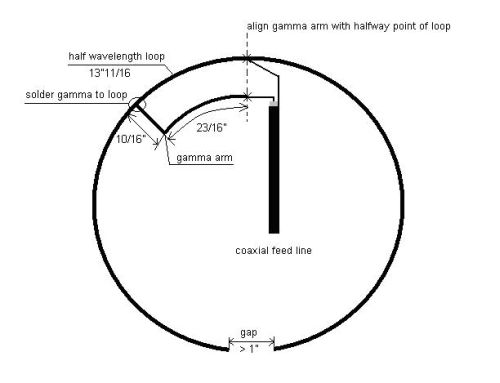
Start by cutting a piece of copper tubing per the dimensions in the diagram above. The easiest way I've found so far to bend this piece of tubing into the correct shape, is to use a tapered flower pot. First I bend the tubing around the widest part of the pot and then move towards the tapered end until the gap is just over an inch wide. Then bend the gamma arm as shown in the diagram above and solder it to the inside of the loop. You can fill the ends of the loop with some RTV to keep the bugs and water out. Make all 4 loops in advance.
Solder a few feet of 50 ohm coax, with a suitable connector on one end, to the gamma match of one of the loops. This is needed to tune the loop. Now attach the hull of a Bic pen near the top of the PVC pipe with two large cable ties. Place the loop on this small support boom and fasten it with 4 small cable ties. The Bic pen support should be near the gap in the loop and the PVC pipe should be on the side of the gamma match. Here are some pictures to clarify the mount:
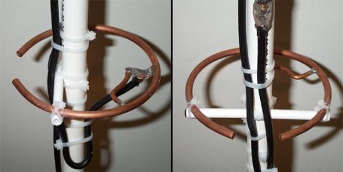
These pictures are taken from the final product and have the phasing harness already in place.
Take the assembly outside for tuning. Place it so that there are no metallic objects nearby that could detune the loop. Tune the loop with either an antenna analyzer or a SWR meter and a transmitter (identify properly!). If you followed the dimensions given earlier, the loop should be resonant (X is near zero on the analyzer) near 432.1 Mhz and the SWR should be very low. If not, then you can increase the resonance frequency by bending the loop a bit so that the gap increases in size. To lower it, make the gap smaller. The gaps in my loops turned out to be 1.25" for resonance.
Take the loop from the support, desolder the coax and solder it to the next loop and mount that one to the support. Tune all 4 loops this way, one at a time.
Connector Bracket
To connect the feed line to the 4 stack I used an SO-239 connector mounted on the PVC support. An N-connector would be better but that may not be readily available. I made a small bracket from a piece of aluminum to mount the connector on and then mounted the bracket to the PVC support pipe using three large cable ties. This image will give you all the information you need to make yours:
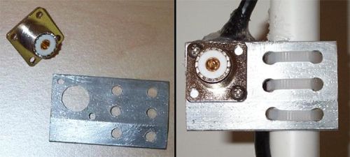
I used a piece of carpet guard to make my bracket, but anything that's not too flimsy will do. The bracket should be made a bit wider than the diameter of the PVC pipe and the connector added together. On one half of the bracket drill the holes to fit the SO-239 panel mount connector and on the other half drill three rows of two holes to fit the cable ties. The distance between the holes where the cable ties go through should be a tad closer together than the diameter of the PVC pipe. This will give maximum friction on the pipe and therefore maximum support.
Mount the connector onto the bracket and then mount the assembly onto the PVC support pipe. The bracket should be halfway up the pipe. Having the connector already in place on the support makes it easier to assemble the phasing harness later.
Phasing Harness
The phasing harness I used consists of 6 pieces of RG-59 coax. Each piece of coax needs to be an odd multiple of a quarter wavelength for the frequency you built the antenna for (432.1 MHz in this case). There are several ways you can construct a phasing harness. Some designs use .25 and .75 wavelength pieces of coax to build a harness, but then your gamma matches have to be on opposite sides. Stacking 4 antennas this way can get confusing and mistakes are easy to make.
The method I describe here keeps things simple and balanced. All gamma matches need to be on the same side. Use equal lengths of coax to connect to the loops. You will need 4 pieces of .75 wavelength coax. Each piece connects to a loop. Then we interconnect the top two loops by connecting the free ends of the coax stubs together (braid to braid, center to center). We do the same for the bottom two loops. This way you will form two separate stacks of two loops. Next, use two pieces of 1.25 wavelength coax to interconnect these two stacks to transform the whole system into a large stack of 4 loops. Saving a thousand words:
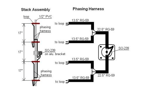
The formula to determine each length of coax attached to each loop is .75 x wavelength x velocity factor. The measurements given in the diagram above are for RG-59 coax with solid dielectric that has a velocity factor of 0.66. If you use foam filled coax you will need to adjust the velocity factor (often 0.88). The length of the two pieces that connect the two stacks together is 1.25 x wavelength x velocity factor.
Cut each length of coax 1" longer than indicated in the diagram above. Remove .5 inch of the outer jacket on each side and expose the braid and center conductor. Presolder the center conductor and braid on each side. Solder each of the .75 phasing stubs to the gamma match of a loop.
You now have 4 loops, each with a .75 wavelength stub attached to it, plus 2 pieces of 1.25 wavelength coax not connected to anything. Do not finish assembling the phasing harness. This is much easier to do after the loops have been mounted onto the PVC support.
Antenna Assembly
Take the PVC support pipe and drill a hole all the way through the PVC pipe at about an inch from each end. These holes need to be large enough to fit the support rope on which the antenna is going to be mounted. See the Tree Friendly 2 meter Halo Antenna page for details on how this antenna mount works.
Mount 4 BIC pen hulls on the PVC pipe using two large cable ties for each hull. One of the hulls may still be on the pipe from when you tuned the individual loops. Mount the supports 17" apart from each other. Make sure that the SO-239 connector is centered between the two supports in the middle, and that all supports are aligned in parallel. Now take each loop with the stub attached to it and mount it onto the small supports using 2 small cable ties on each side. The part of the loop with the gap should be on the side of the pipe with the BIC pen support. The gamma match should be on the other side of the pipe. All gamma matches need to be on the same side, so all loops are mounted the same way. See the diagram in the Phasing Harness section to get an idea of what the final assembly is supposed to look like. The pictures in the Loops section will show you how the individual loops are mounted.
Attach the coax stubs coming from the loops to the PVC support with some cable ties. Make sure the ends of the stubs of each 2-stack meet just above the bottom loop of each stack (see diagram above). You will notice that each stub will also act as a third support point for the loop. Moving the stub up and down will change the angle between the loop and the PVC support pipe. The loop should be perpendicular to the PVC support. You can solder the two stubs of each 2-stack together. The braids should be soldered together and the same goes for the two center conductors.
Now take the two 1.25 wavelength stubs you have still left and solder them in parallel to the SO-239 connector. The center conductors need to be soldered to the center pin of the connector and the two braids need to be soldered to a solder lug that is fastened to one of the bolds that holds the connector onto the bracket. Then tie these stubs to the PVC support so that each end will reach the point where the two .75 wavelength stubs come together. Solder the center conductor to the center conductors of the smaller stubs and do the same for the braids. Do this for both top and bottom stack. You now have a complete 4 stack halo antenna for 70cm and it should look something like this:
Weather Proofing
To weather proof the antenna use liberal amounts of RTV everywhere an electrical connection is made. The two images below show you how I sealed the phasing harness connections (left) and the back of the SO-239 connector (right).
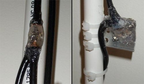
Don't forget to seal the coax on the gamma matches with RTV. You don't want water to be able to get anywhere into the coax. To make sure that the cable ties don't slip, put a drop of super glue where the cable ties and the other surfaces meets.
You probably noticed I used white cable ties. If you intend to mount the antenna somewhere permanently you really should be using black cable ties as these stand up better against exposure to UV radiation. I used white ties mainly because I was prototyping this antenna and that was all that I had available at the time.
Once the PL-259 connector on the feed line is joined with the SO-239 connector, wrap the PL-259 in some electrical tape. Then wrap some coax sealant over the electrical tape and mold it so it makes for a water tight seal. The electrical tape is there so you can easily remove the coax sealant if you ever have to disconnect the feed line. You can simply cut through the sealant and cut the tape. When you peel off the tape, the sealant will stay on the tape and not on the connectors and coax, which will prevent a big mess.
Joining the Antenna Orchard
Once the RTV has fully cured you can mount the antenna on a support rope in the tree. Put the support rope through the top holes in the PVC pipe and tie it off. Raise the antenna so the SO-239 connector is about 4 feet off the ground. Attach the feed line and seal the connection as described above. Route the feed line through the bottom two loops on the side with the gaps. Tie the feed line to the PVC support with some large cable ties.
Take a second piece of rope and put that through the bottom holes in the PVC pipe and tie that one off, too. Raise the antenna a bit more and fasten the feed line to the bottom rope with cable ties. Do this every foot or so until you are 6 feet below the antenna. After that you can route the coax however you want to your operating position.
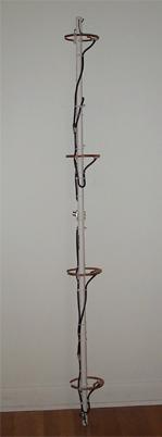
Continue to raise the antenna to the position where you want it. Now tie a heavy weight to the bottom rope at about a foot above the ground. I've used a brick with good success. Your antenna is now ready for use:
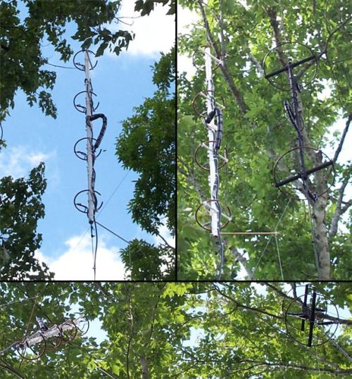
The pictures above show you how my antenna is currently mounted. The 70cm stack is at least 10 feet away from the 2 meter stack, although it looks a lot closer in the pictures. The 2 meter stack is also almost 10 feet higher than the 70cm stack.
You probably noticed that there's a stick protruding from the bottom of the PVC support. After observing the antenna in a bit of wind, I noticed that it rotates quite a bit around the vertical axis when the wind speed gets over 10 mph. To combat this I drilled a hole through the bottom of the PVC support and drove a skewer through it. At the end of the skewer I attached some 30 pound strength monofilament fishing line. Near ground level I attached a weight (plastic bottle with some rocks in it) to the fishing line and guided the line through a pulley mounted on a fence post. This way the weight can move freely just like the antenna, and it keeps the antenna steady in the wind.
Conclusion
I did some comparative testing with a good friend of mine. In the past I have used the 2m stack on 70cm, but I could never copy him very well. On the 2m stack I could hear him just above the noise level. Switching to lower mounted 70cm stack increased his signal by 4 S units. During the ARRL VHF QSO party I was able to hear DX stations (over 120 miles) for the first time on 70cm. It's very nice to finally be able to hear some activity on that band and to be able to make some reliable contacts.
The antenna is certainly cheap. I built the antenna from scraps I had laying around, but I doubt it would cost more than $20 to purchase all parts. The hardest to find item will be the SO-239 connector, which you can find at your local Radioshack. You also don't need a well equipped shop to build it.
Even though the construction may not seem very sturdy, it seems to be holding up very well in the elements. The antenna has been exposed to torrential rains and has seen wind speeds upwards from 40mph. At times I was sure I'd find parts of it all over the backyard, but so far it's performing like on the day I installed it.
If you're in a situation where you, like I, live in an area with so little UHF activity that it doesn't warrant an expensive rotatable antenna system, give this Halo 4-stack a shot. It may also provide for a good portable antenna as it can easily be mounted on a small mast on a tripod for hill topping or roving. You can also easily mount this antenna in the attic.
Now when they ask me in a VHF+ contest if I have 432, I can say "where do you want to go?". That's a lot more exciting than "sorry, no antenna".
If you have any questions or suggestions, please do not hesitate to drop me an email.
73,
--Alex, KR1ST